Introduction
Let’s be honest, if you’re here it’s probably because you found this blog on Google. As I understand it, at the moment there are no comprehensible resources to use ROS2 with the Coppelia simulator (previously known as V-REP), and it is no simple task.
In this tutorial, we will make a simple project using a Pioneer P3DX with a Lidar, in which we will use Slam Toolbox to create a map of the room, all using ROS2 tools like RVIZ2 and NAV2’s Slam Toolbox, but using Coppelia as a simulator instead of Gazebo.
The end product will look something like this:
I made it work but I’m no expert in robotics, so if I made some error, please let me know in the comments or on GitHub.
I will center on the programming part because the way of adding a robot and lidar is the same whether you’re using ROS2 or not.
The original project was made as homework for the Master Universitario en Inteligencia Articial (MUIA) at Universidad Politécnica de Madrid (UPM)
Installing simExtROS2
ROS2 works by creating publishers and subscribers that emit and receive messages of a message type. To be able to do this from Coppelia, we will use the module simExtROS2.
Coppelia comes with this module installed, but it’s compiled with too few message types embedded. If you try publishing some sensor data, it will fail. You need to modify a config file from the source code and compile it again so it supports that message type.
First, we will download the source code. Because I’m using Coppelia 4.4.0, I’ll checkout to that version too. Feel free to change the version number if you need to.
git clone --recursive https://github.com/CoppeliaRobotics/simExtROS2.git
# according to the docs, we have to rename the folder
mv simExtROS2 sim_ros2_interface
git checkout coppeliasim-v4.4.0-rev0
Before compiling, we need to modify a config file to specify the message types you want to compile. This file is meta/interfaces.txt, and in my case, it ended up with the following contents:
meta/interfaces.txtbuiltin_interfaces/msg/Duration
builtin_interfaces/msg/Time
rosgraph_msgs/msg/Clock
geometry_msgs/msg/Quaternion
geometry_msgs/msg/Transform
geometry_msgs/msg/TransformStamped
geometry_msgs/msg/Vector3
geometry_msgs/msg/Point
geometry_msgs/msg/Pose
geometry_msgs/msg/PoseStamped
geometry_msgs/msg/Twist
geometry_msgs/msg/PoseWithCovariance
geometry_msgs/msg/TwistWithCovariance
sensor_msgs/msg/Image
sensor_msgs/msg/PointCloud2
sensor_msgs/msg/PointField
sensor_msgs/msg/LaserScan
std_msgs/msg/Bool
std_msgs/msg/Byte
std_msgs/msg/ColorRGBA
std_msgs/msg/Empty
std_msgs/msg/Float32
std_msgs/msg/Float64
std_msgs/msg/Header
std_msgs/msg/Int8
std_msgs/msg/Int16
std_msgs/msg/Int32
std_msgs/msg/Int64
std_msgs/msg/String
std_msgs/msg/UInt8
std_msgs/msg/UInt16
std_msgs/msg/UInt32
std_msgs/msg/UInt64
std_srvs/srv/Empty
std_srvs/srv/SetBool
std_srvs/srv/Trigger
nav_msgs/msg/Odometry
Ultimately, you will have to add the following environment variable, either modifying ROS’ setup.bash or your .bashrc.
export COPPELIASIM_ROOT_DIR="<your coppelia installation path>"
Now we can proceed to compile and install the library
Compiling libsimExtROS2
After downloading everything, we can install it with Colcon, using the following command:
colcon build --symlink-install
This will take lots of resources and will take up a while the first time, but don’t worry, it will finish and install it.
Modifications in Coppelia
Publishing the simulation time
We can’t use a “wall clock” because the simulation is not in real-time. Let’s imagine
you implement an odometry module, and you try to calculate your speed by subtracting
your current position from a previous position and dividing by the number of seconds
elapsed. This formula will be wrong if your simulation is a bit slow, or if it is too fast.
That’s why we need to publish Coppelia’s simulation time into the topic /clock.
function sysCall_init()
  ...
  simTimePub=simROS2.createPublisher('/clock','rosgraph_msgs/msg/Clock')
  ...
end

function sysCall_actuation()
  ...
  t=sim.getSimulationTime()
  simROS2.publish(simTimePub, {clock={
    sec=math.floor(t),
    nanosec=(t-math.floor(t))*10^9}}
  )
  ...
end

function sysCall_cleanup()
  ...
  simROS2.shutdownPublisher(simTimePub)
  ...
end
Publishing transforms
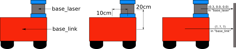
The transforms allow ROS modules to calculate the exact distance between any two objects, publishing just the partial distances. For example, we can publish the distance of the laser’s reference frame to the robot, and ROS can able to calculate the distance from the laser to anything automatically.
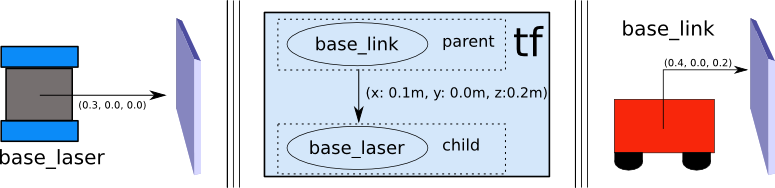
Each published transform has a parent, and the root of this hierarchy is the transform that is not published (it is just referenced as a parent). According to the standard REP105, this root should be world or map if we have just one robot.
We will publish the following transforms:
- From the lidar frame to the robot frame
- From the robot to the odometry frame
- From the wheels to the robot frame (needed to display the robot in the simulator)
The final transform, from the odometry frame to the world map is published by another module, so we won’t send it from Coppelia.
To publish all these transforms, we use the following code (remember to change the constants as needed):
function getTransformStamped(objHandle,name,relTo,relToName)
  p=sim.getObjectPosition(objHandle,relTo)
  o=sim.getObjectQuaternion(objHandle,relTo)
  return {
    header={
      stamp=simROS2.getSimulationTime(),
      frame_id=relToName
    },
    child_frame_id=name,
    transform={
      translation={x=p[1],y=p[2],z=p[3]},
      rotation={x=o[1],y=o[2],z=o[3],w=o[4]}
    }
  }
end

function sysCall_actuation()
  ...
  simROS2.sendTransforms({
    getTransformStamped(robotHandle, ROBOT_FRAME_ID, -1, PODOM_FRAME_ID),
    getTransformStamped(leftWheel, 'Pioneer_p3dx_leftWheel', robotHandle, ROBOT_FRAME_ID),
    getTransformStamped(rightWheel, 'Pioneer_p3dx_rightWheel', robotHandle,ROBOT_FRAME_ID),
    getTransformStamped(caster_link, 'Pioneer_p3dx_caster_link', robotHandle, ROBOT_FRAME_ID),
    getTransformStamped(caster_wheel, 'Pioneer_p3dx_caster_wheel', caster_link, 'Pioneer_p3dx_caster_link'),
    getTransformStamped(sensorRefHandle, SENSOR_REF_FRAME, robotHandle, ROBOT_FRAME_ID),
  })
  ...
end
Publishing Lidar PointCloud
The lidar we used returns a PointCloud in Coppelia’s signal Pioneer_p3dx_lidar_data. This PointCloud is an array of triplets of floats, each triplet representing the x, y and z coordinates of each point. We want to publish this data in a topic of type sensor_msgs/msg/PointCloud2.
This message needs us to send a stream of binary data and specify the type of this data in the parameter fields. We will see exactly how with the following commented code:
function sysCall_init()
  ...
  lidarDataTopicName = '/lidarPC'
  lidarDataPub=simROS2.createPublisher(lidarDataTopicName, 'sensor_msgs/msg/PointCloud2')
  ...
end

function sysCall_actuation()
  ...
  lidar_signal = 'Pioneer_p3dx_lidar_data'

  -- Get binary data from signal
  data = sim.getStringSignal(lidar_signal)

  if (data == nil or #data == 0) then
    -- It's normal for this to happend in the first iteration of simulation
    sim.addLog(sim.verbosity_scripterrors, 'signal name ' .. lidar_signal .. ', returned nil value')
  else
    -- Unpack binary data as array of floats
    floats = sim.unpackFloatTable(data)

    -- Each point is 3 floats, so the number of points
    -- is number of floats / 3
    n = #floats//3

    simROS2.publish(lidarDataPub, {
      header={
        stamp=simROS2.getSimulationTime(),
        frame_id='lidar_ref_frame',
      },
      height=1,
      -- Number of points (not bytes)
      width=n,
      -- Each point is 3*4 = 12 bytes
      point_step=12,
      fields={
        -- datatype 7 is FLOAT32
        -- the offset is in BYTES
        {name='x', offset=0, datatype=7, count=1},
        {name='y', offset=4, datatype=7, count=1},
        {name='z', offset=8, datatype=7, count=1},
      },
      -- Unpack data as bytes (uint8)
      data=sim.unpackUInt8Table(data),
    })
  end
  ...
end
After all of this, the PointCloud message will be available on the topic /lidarPC
Setting the robot’s speed
In this case, instead of a publisher, we will need to create a subscriber that receives a message of type Twist. This message contains the desired linear and angular velocities.
We need to convert this to the angular velocity of the motors of the wheels, so, after applying some basic arithmetics, we get the following code:
function sysCall_init()
  ...
  velSub = simROS2.createSubscription('/cmd_vel', 'geometry_msgs/msg/Twist', 'setVelocity_cb')
  ...
end

function setVelocity_cb(msg)
  -- The message provides linear velocity in m/s
  -- but coppelia receives it in rad/s, we need to convert it
  linear = msg.linear.x
  angular = msg.angular.z

  -- https://www.inf.ufrgs.br/~prestes/Courses/Robotics/manual_pioneer.pdf
  wheel_radius = 0.195 / 2 -- 19.5 cmm
  robot_width = 0.33 -- 38 cm minus wheel width
  vl = linear - (angular * robot_width) / 2
  vr = linear + (angular * robot_width) / 2

  sim.setJointTargetVelocity(leftMotor, vl / wheel_radius)
  sim.setJointTargetVelocity(rightMotor, vr / wheel_radius)
end
ROS2
The main advantage of using ROS2 instead of programming the behavior of our robot directly on Coppelia is that ROS2 is platform agnostic and we can use it with any simulator, and even with a real robot.
The system has just 3 nodes:
pointcloud_to_laserscan: It transforms the data from type Pointcloud2 to LaserScan so Slam Toolbox is able to use it.async_toolbox_node: Makes a map and localizes the robot in the map.teleop_twist_keyboard: Allows us to move the robot
You’ll need to install them before proceeding
Running the nodes
The easiest way by far is to open three terminals and run the command to start the node in each one. The order doesn’t really matter as nodes usually wait for the info to become available.
Remember to source the ROS
setup.bashfile to make theros2command available!
We’ll use the following bash command This will create a new topic called Starting
pointcloud_to_laserscanros2 run pointcloud_to_laserscan pointcloud_to_laserscan_node --ros-args \
-p use_sim_time:=true \
--remap cloud_in:=/lidarPC
/scan with the data converted.
We need to specify the name of the frames (remember to change the name of the frames if you changed them) This will create a Starting
async_toolbox_noderos2 run slam_toolbox async_slam_toolbox_ndoe --ros-args \
-p base_frame:="base_link" \
-p odom_frame:="odom" \
-p map_frame:="map" \
-p scan_topic:="/scan" \
-p use_sim_time:=true
/map topic
We don’t need to modify anything, so the command is just This will send the velocity commands via the Starting
teleop_twist_keyboardros2 run teleop_twist_keyboard teleop_twist_keyboard
/cmd_vel topic
Conclusion
Finally, you can open rviz2 and start adding visualizations to visualize the map that SLAM Toolbox created, you can also visualize the position and velocity of the robot, and even the PointCloud and LaserScan!
Using the teleop_twist_keyboard you can move the robot around, and the map will change
in real-time. Pretty fun to drive. If you want, you can try with other nodes, or even
create your own to make the robot move autonomously.
If you have any doubts, feel free to leave a comment or open an issue on GitHub. If you already know a bit about robotics and you detect some mistake that I made, please tell me so and I’ll modify the post. Thank you for reading me and see you next time!
Sources and more information
- ArchWiki - ROS. On how to install ROS and solve problems in ArchLinux / Manjaro.
- CoppeliaSim User Manual. One of these things that is not on google, but solves a lot of problems.
- GitHub - coppeliaRobotics/simExtROS2. In the “Issues” part there are some interesting problems and solutions.
- ROS Planning. Setting Up Transformations. NAV2 documentation is overall a good source material to understand how ROS works.
- REP 105 – Coordinate Frames for Mobile Platforms